Get in Touch with SINOFUDE Company
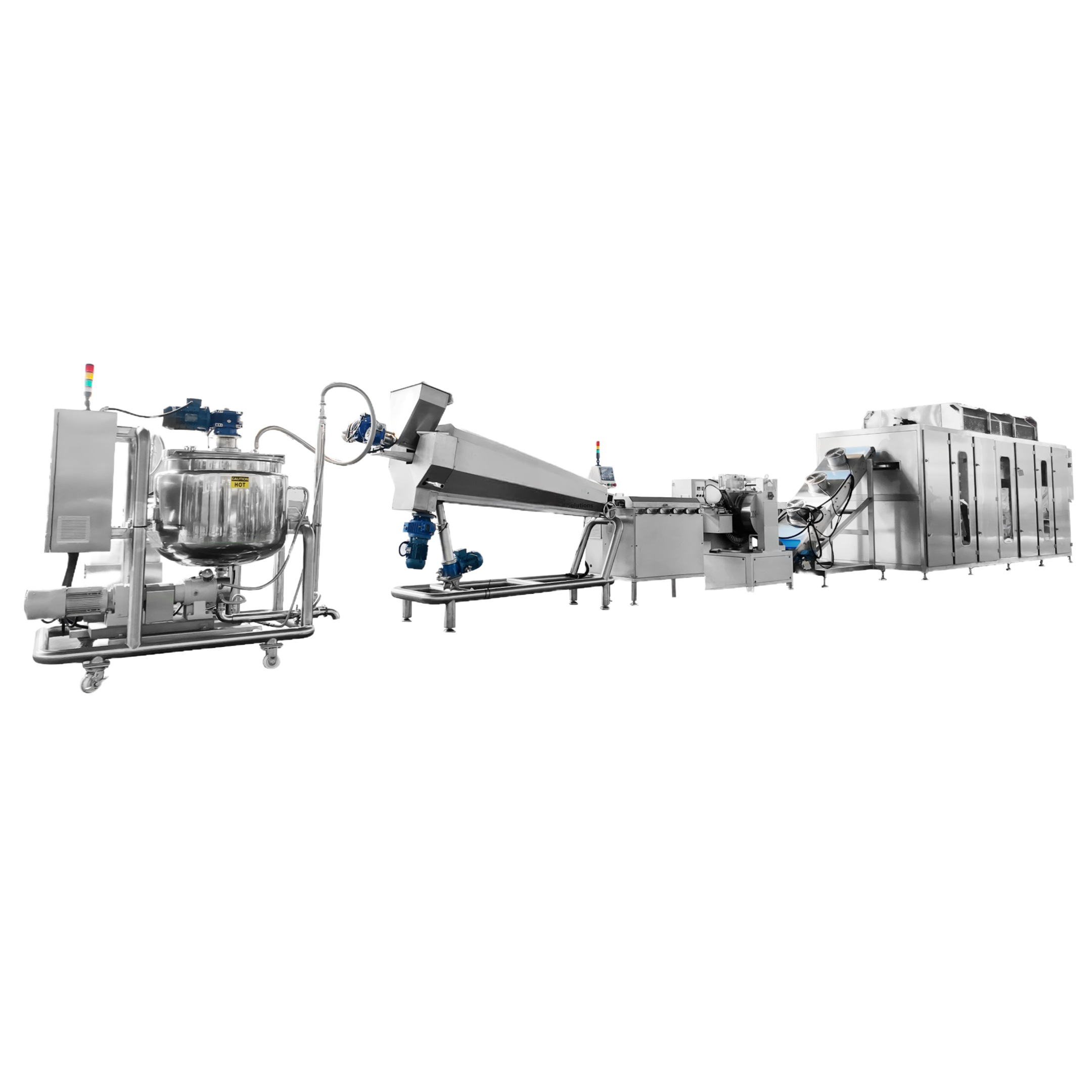
Lollipop Machine for Industrial Candy Production
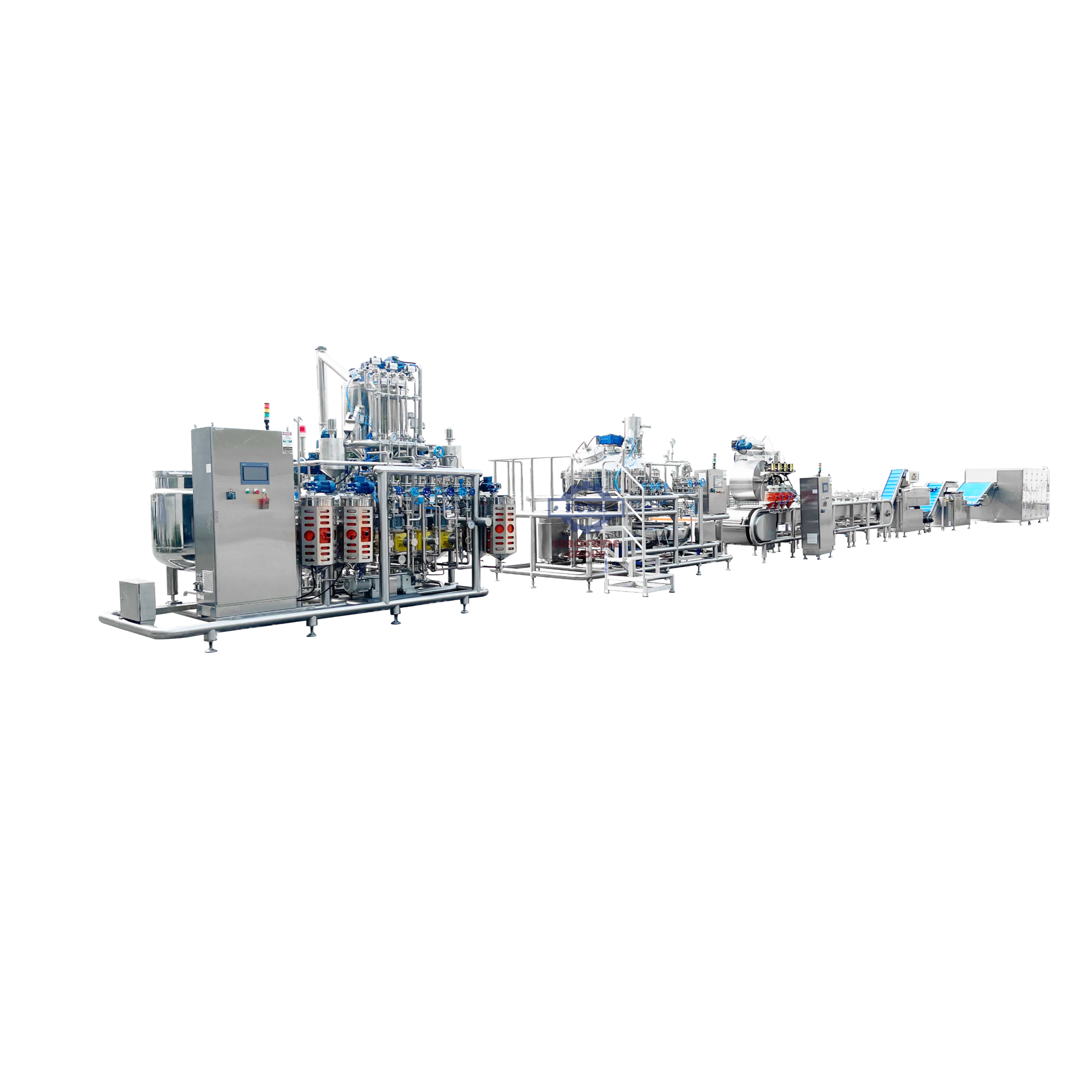
We configure a lollipop making machine around your candy mass, product shape and line boundary. We connect the lollipop forming, stick and mould interfaces with cooling, packing and utilities to make your brief a reviewable plan.
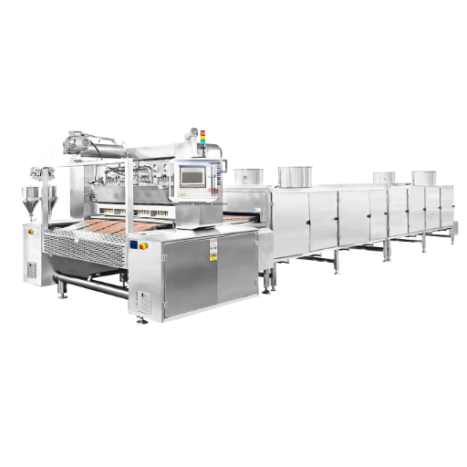
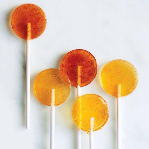
Ball and flat formats
Depositing or die-forming route
Cooling and release review
Engineer-led configuration
Lollipop Line Fit at a Glance
Headline speed can hide cooling limits and create a capacity mismatch because the same reference rate may produce a different result at another piece weight. For that reason, we keep the SINOFUDE series and its 150-600 kg/h range tied to the project acceptance criteria. Our review confirms the usable output against the project test basis.
CYTB150, CYTB600 deposited-lollipop range
150–600 kg/h, recalculated for your product
25–35 strokes/min, tied to the agreed test basis
Ball or flat mould architecture
Cooking, forming, cooling and wrapping interfaces are confirmed per project
Piece weight, cavities, recipe, cooling and sampling method
Our Lollipop Forming and Depositing Capabilities
We choose a depositing or die-forming route after a thorough assessment of the candy mass, shape, color architecture, and output brief. From that point, we specify the machine scope so we never assume that an upstream cooker, stick system, downstream cooler or wrapper is in scope without confirmation.
Our lollipop forming machine review covers briefs for both a ball lollipop machine and a flat lollipop machine, while the parent page retains the commercial lollipop production line intent.
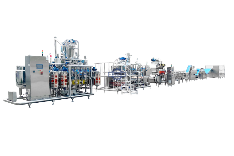
Deposited lollipop route
For this route, we match the hopper, pistons, manifold and nozzles to viscosity, cavity layout and centre-fill or layered designs. Indexing and stick placement are coordinated with the depositing cycle.
Die-formed lollipop route
During route review, we examine cooked-mass conditioning, rope or batch forming, die geometry and stick insertion as one sequence. The drawing and sample define the forming window.
Cooling and release
Before layout freeze, we define cooling residence, release condition and transfer points. Demoulding connects to wrapping or bulk packing only when that interface is in scope.
Line integration
A route map lets us place utilities, controls, guarding and operator access around the selected equipment. Open interfaces for cooking, cooling, packing and site services are documented with your team.
Capability facts we use in a review
- For ball and flat lollipop formats, we configure separate product bases.
- Across the forming cycle, our design aligns mould cavities with depositing and stick timing.
- Against the recipe window, our team adapts the head and manifold.
- By project boundary, cooking, forming, cooling and packing responsibilities stay separate.
- Before acceptance, our engineers define the cooling and release condition.
- For colour, layer and centre-fill products, the feed architecture is planned from the sample.
- Within the layout, utility and equipment interfaces are documented.
- As route inputs, product samples or drawings remain central to our review.

Candy Mass and Product Architecture Inputs
A recipe name alone can create a selection risk. Forming temperature, solids content and viscosity can affect dosing stability. Before we freeze the FAT acceptance criteria, we record these inputs.
At intake, we record hard-candy, toffee, fondant or another declared family, then connect temperature and solids data to the route.
Cooling, Release and Hygiene Interfaces
Cooling that is sized from headline output alone risks condensation, stickiness and failed release because recipe and geometry set the real heat load. During engineering review, we compare the SINOFUDE route with the product trial, ISO 14159 design questions and FAT acceptance criteria.
Release condition
For stable mould release, our engineers define the required temperature and surface state.
Cleanable access
Product-contact and splash zones are identified with smooth, reachable cleaning paths in mind.
Safeguarding review
Point-of-operation guarding, energy isolation and operator access are included in our design review.
Quotation Scope and Configuration Basis
A hidden line boundary creates rework, delay and avoidable cost because a forming-machine quote can be mistaken for a complete production line. In the proposal, we separate 4 interface groups: cooking, forming, cooling and packing, then write the acceptance criteria and exclusions into the configured scope.
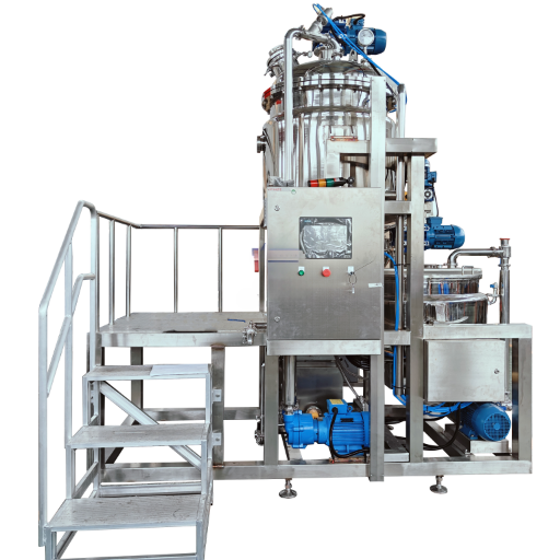
What moves the configuration
| DRIVER | CONFIGURATION EFFECT | HOW WE REDUCE UNCERTAINTY |
|---|---|---|
| Shape and cavity layout | Changes mould, indexing and stick timing | Send a drawing or product sample |
| Recipe and viscosity | Changes heated transfer, head and nozzle selection | Share temperature and viscosity window |
| Cooling and release | Changes residence, demoulding and transfer design | Define release condition and sampling method |
| Line boundary | Changes upstream, downstream and utility scope | Mark cooker, wrapper, services and controls ownership |
Quality, Compliance and FAT Coordination
We build acceptance around the declared product and the documented test basis. Throughout the record, brand facts remain separate from project-specific FAT results.
FAT control points
Before testing, our team agrees the recipe, weight, speed, sampling duration, reject criteria, synchronization, guarding and changeover demonstrations.
Our company record
In the company profile supplied for this page, we record 1998 as our founding year and describe three factories, more than 200 employees, and a combined footprint of more than 30 acres. Buyers can request current documentary support during qualification.
Management and product evidence
That same profile records an ISO9001 management system introduced in 2004 and 38 product patents. We treat current certificate scope and patent-status evidence as due-diligence documents, not as blanket claims on this page.
Our inspection sequence
- 01 Against the approved brief, our team reviews the drawing, recipe and cavity plan.
- 02 During the dry run, motion, guarding and energy-isolation provisions are verified.
- 03 With the agreed product, our engineers observe depositing or forming stability.
- 04 For sign-off, cooling, release, sampling and open actions are recorded.
From Product Brief to FAT
Late changes are expensive because a new product basis can affect the mould, head, cooling and controls together. Our 6-step SINOFUDE review keeps the drawing, process assumptions and FAT acceptance criteria in one traceable sequence. In our project sequence, FAT is the factory-stage check; installed connections and operation are checked separately during site acceptance or commissioning when those services are included in the contracted scope.
We collect shape, piece weight, target output, recipe notes and site details.
We map depositing or die-forming against mass behaviour and product architecture.
We define mould, stick, head, cooling and downstream interfaces.
We review utilities, guarding, access and responsibility boundaries.
We issue the configured scope and record agreed exclusions.
We test the agreed basis and return traceable records and actions.
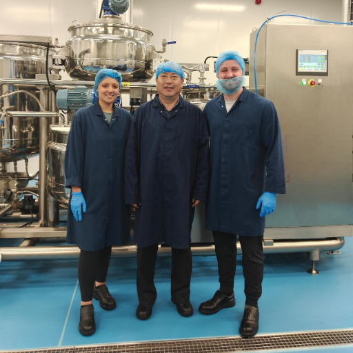
Design notes that protect your budget
| Design feature | What to specify | Why it helps |
|---|---|---|
| Product geometry | Ball or flat profile and cavity pitch | Prevents late mould and timing changes |
| Recipe window | Temperature, solids and viscosity notes | Prevents unsuitable head or transfer choices |
| Cooling target | Residence and release condition | Reduces rework caused by unstable release |
| Site interface | Utilities, layout and packing boundary | Limits change orders at installation |
Engineering Evidence We Can Review
Unsupported catalog claims create a verification gap because a reference range does not define the tested product. As starting evidence, we use 2 supplied SINOFUDE engineering documents and transform their inputs into project-specific FAT acceptance criteria.
“Final equipment layout is customized to the product, output and site conditions.”
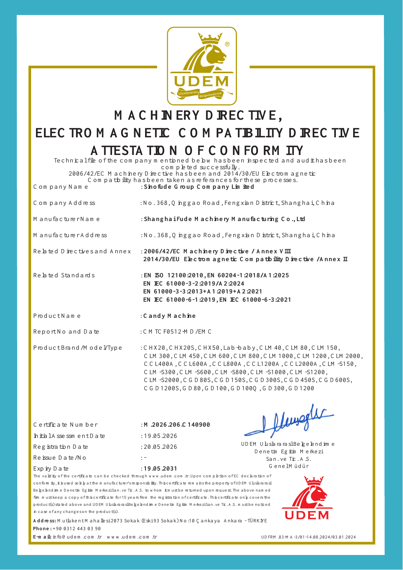
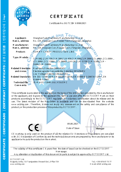
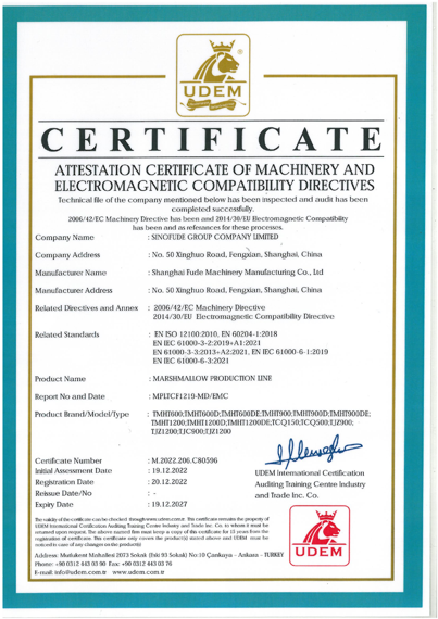
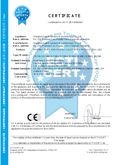
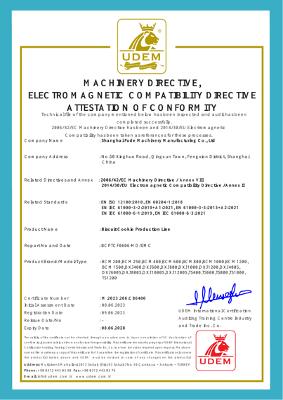
Document trail
In one controlled brief, our team can review your drawing, sample, recipe notes, utilities and layout.
Acceptance trail
At FAT, the agreed speed, weight, cooling and sampling basis is recorded with open actions.
When a Standard Route Needs Re-Scoping
Higher speed is not always higher usable output, one mould is not always interchangeable between formats, and more modules are not always the lowest-risk scope. The trade-off depends on recipe behavior, weight, cavities, cooling and the available line space.
SITUATION
WHY IT CHANGES THE ROUTE
WHAT WE DO INSTEAD
-
Situation: Multiple colours or centre fillingWhy it changes the route: Independent feeds, manifolds and controls may be requiredWhat we do instead: A layered-sample review lets us define the feed architecture
-
Situation: New cavity pitch or piece weightWhy it changes the route: Mould timing and output basis change togetherWhat we do instead: A recalculation sets the revised mould and test basis
-
Situation: Cooling space is fixedWhy it changes the route: Residence time and release may not fit the layoutWhat we do instead: A layout review or sample trial comes before design freeze
Engineering Planning & Assessment Tools
Lollipop Machine FAQ
Can one line make ball and flat lollipops
Both routes can be reviewed, but the mould, stick timing, head and cooling basis must match each format.
From your samples and cavity plan, we confirm the changeover scope.
How do we confirm actual capacity
Our engineers start with the CYTB150–CYTB600 reference series, its 150–600 kg/h capacity and 25–35 strokes/min speed.
We then recalculate output against piece weight, cavity count, recipe, depositing rate and cooling time.
What should I send for a quotation
Send a product sample or drawing, target piece weight, hourly output, recipe and viscosity notes.
Include colour or centre-fill design, mould plan, electrical standard, utilities, layout and package style.
When does the depositing head or mould set change
A change review begins when geometry, cavity pitch, weight, colour architecture or recipe conditions move outside the approved basis.
Before releasing a revised configuration, our team records the new basis.
Can wrapping be included
A wrapper or bulk-packing interface can be mapped when it is in the project scope.
Clear boundary labels keep cooking, cooling, controls and packing ownership visible to both teams.
What does FAT cover
Before the test, our teams agree the product, weight, speed, sampling duration, reject criteria, synchronization, guarding and changeover points.
We record the result and open actions at the factory; installed checks remain a separate contracted scope.
How do we plan utilities
Before line-concept freeze, we collect the destination jurisdiction, electrical standard, utilities, drainage, cooling service and available layout.
Safeguarding and energy isolation remain design inputs.