Get in Touch with SINOFUDE Company

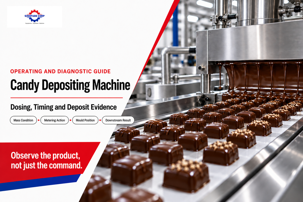
A Candy Depositing Machine is equipment that shapes candy by metering prepared mass and carefully placing it into molds. The operation relies on multiple factors to consistently make repeatable pieces. This guide provides operating and troubleshooting tips. This isn’t a manual for product models, pricing, or other sales related information.
Read the evidence chain firstRecord the recipe and mass condition, commanded and observed metering action, nozzle cut-off, mould position, cavity-level piece weight, and downstream result before changing a setting.
Updated September 2026. In general, replace the advice in this document with procedure and criteria accepted by your organization.
What Does a Candy Depositing Machine Actually Control?
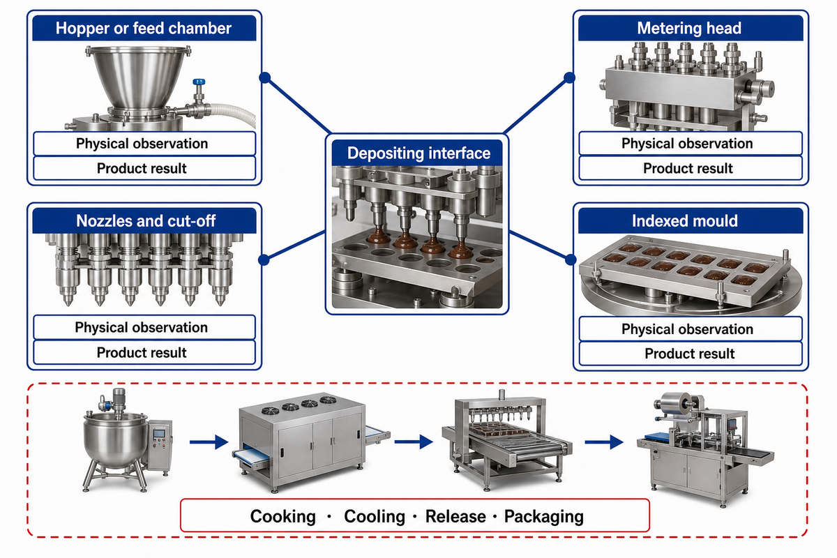
Forming candy to a particular shape is a manufacturing process that begins when candy is metered through a head into a mold and ends when the piece is released from the mold. [process source] In the U.S., the word “mold” is also often spelled as “mould.”
| Component | Controlled function | Evidence to observe |
|---|---|---|
| Hopper or feed chamber | Presents mass to the metering system | Level, hold condition, bubbles, pause history |
| Metering head | Moves the selected dose | Command, actual motion, repeatability, seals |
| Nozzles and cut-off | Shapes the start and end of flow | Tail, drip, blockage, close behavior |
| Indexed mould | Presents each cavity | Pitch, alignment, deposit position |
In a continuous operation, one key challenge is getting conditioned candy across the depositing interface in a shape that conforms to the mold. The design of the manufacturing system, equipment, and other process controls dictates the steps in a process and the order in which they’re performed.
Boundary check: A good deposit does not prove that cooking, cooling, release, or packaging is qualified. It proves only what the agreed sample and test method can show at the measured interface.
The Seven-Step Deposit Cycle
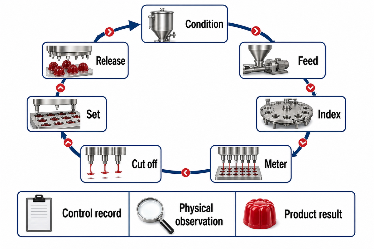
Because functionality and controls vary by system and equipment, a different order of steps may be performed in the process. [process source]
1. Condition
Identify the recipe, batch, mass state, and hold history.
Identify the recipe, batch, mass state, and hold history.
2. Feed
Keep the presented mass stable enough for metering.
Keep the presented mass stable enough for metering.
3. Index
Bring the intended cavity into the commanded position.
Bring the intended cavity into the commanded position.
4. Meter
Move the selected amount through the head.
Move the selected amount through the head.
5. Cut off
Start and end the stream at the required points.
Start and end the stream at the required points.
6. Set
Cool or set enough for the next interface.
Cool or set enough for the next interface.
7. Release
Transfer the piece while preserving accepted form.
Transfer the piece while preserving accepted form.
Controls and commands issued don’t necessarily correspond to the state of the physical system being controlled. It’s important to continuously monitor the physical system to determine whether candy has taken the intended shape in the mold.
Observation rule
Pair one control record with one physical observation and one product result. When those three disagree, preserve the first affected sample and the machine state before making an adjustment.
Pair one control record with one physical observation and one product result. When those three disagree, preserve the first affected sample and the machine state before making an adjustment.
Why Mass Condition Is a Gate, Not a Universal Number
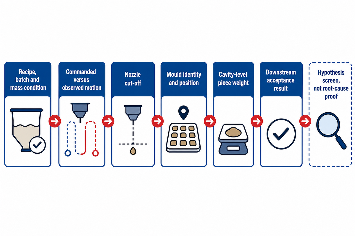
Temperature, flow behavior, solids, crystallization risk, residence time, and pause history are factors that affect process behavior. In addition, the equipment configuration and recipe play an important role. Generally, process conditions can’t be transferred unless the recipe, measurement location, instrument, method, machine state, and other factors are defined. [instrument boundary]
6-Signal Deposit Evidence Chain
Six-Signal Deposit Evidence Chain
- Named recipe, batch, and measured mass condition
- Commanded versus observed metering stroke or cycle
- Nozzle cut-off, drip, tail, or suck-back observation
- Mould identity and position at deposit
- Cavity-level piece-weight sample with method
- Cooling, release, and downstream acceptance result
The chain can help work centers identify possible mass issues. It’s essential to preserve observations, narrow possible causes, and verify appropriate corrective actions without treating the chain as root-cause proof.
Use the chain to
- find where command and outcome diverge
- choose a controlled comparison
- preserve evidence before adjustment
Do not use it to
- declare a single cause from correlation
- ignore interacting factors
- transfer a setpoint between recipes
In a designed experiment, it’s important to keep all the other factors the same. If the recipe, operator, mold, surrounding conditions, and the state of the process control system (PCS) are different, an improved process outcome is useful information, but it doesn’t distinguish between possible causes.
How the Metering Head, Nozzles, and Mould Timing Interact
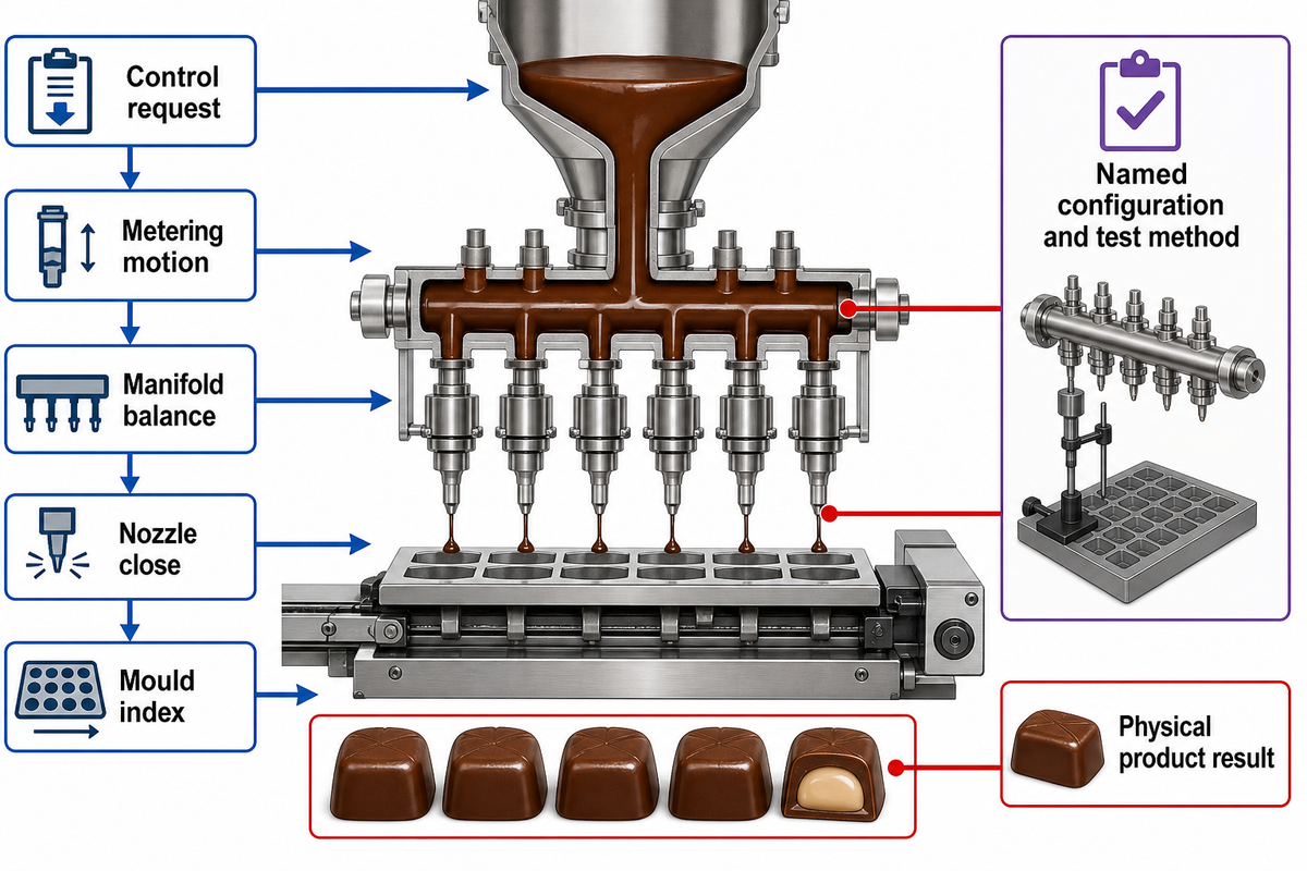
The process control system requests the dosage. The metering system creates and controls process motion. The flow control manifold distributes process fluid to several process nozzles, which are controlled to open and close. The process nozzles control the flow of the process fluid to the mold during the process window. [configuration example]
| Interface | Observable evidence | Failure signal | Next check |
|---|---|---|---|
| Metering motion | Command and actual movement | Short or uneven dose | Stroke, seals, feed state |
| Manifold balance | Cavity pattern across rows | Position-linked weight spread | Flow path and blockage pattern |
| Nozzle close | End of stream | Tail, drip, string | Cut-off action and product state |
| Mould index | Deposit location by cavity | Offset or wall contact | Pitch, alignment, timing |
It’s relevant to evaluate the state of the process control system and mold in use in the same review. These factors play a critical role in process repeatability, but published tolerances require a named configuration and test method.
Commanded is not observed: Keep screenshots or controller exports with cavity samples, not instead of them. The product result is the physical cross-check on the control record. The cited patent is a configuration-specific rotary-valve and piston example, not a category benchmark.
Centre-Fill Is a Shell-Core Interface, Not a Nozzle Add-On
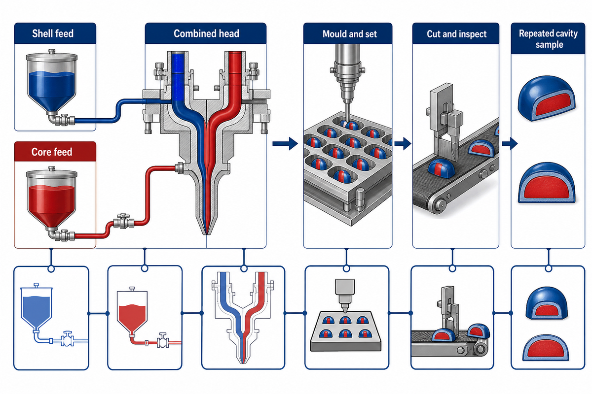
Centre-fill depositing coordinates separate shell and core streams through a combined forming event. Feed condition, relative deposit position, timing, initial shell setting, and section geometry can interact, so adding another passage does not by itself establish a qualified centre-filled product.
Shell feed
Condition and continuity
Condition and continuity
Core feed
Condition and ratio evidence
Condition and ratio evidence
Combined head
Relative position and timing
Relative position and timing
Mould and set
Placement and early support
Placement and early support
Cut and inspect
Section and leakage evidence
Section and leakage evidence
Two patent examples US20050260329A1 and US20130004622A1 illustrate different liquid-centre and timed double-deposit mechanisms, including one lollipop example. They show configuration diversity; their rates, temperatures, layouts, and claims aren’t SINOFUDE specifications.
Acceptance evidence
Define the cut-section location, shell-wall continuity, core location, leakage condition, time of inspection, and repeated cavity sample. A single attractive section cannot establish row-to-row or run-to-run consistency.
Define the cut-section location, shell-wall continuity, core location, leakage condition, time of inspection, and repeated cavity sample. A single attractive section cannot establish row-to-row or run-to-run consistency.
Where the Depositor Sits in the Hard Candy Production Line
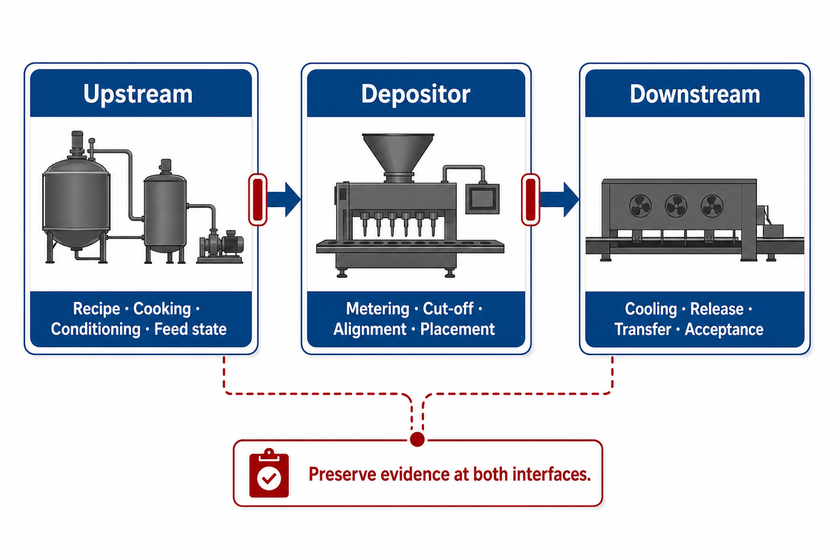
In a continuous production system, the depositor’s role is to accept conditioned mass from an upstream system, place that mass in a mould, and transfer the formed piece to the downstream system for further processing. [process source] The throughput of the downstream system can constrain line speed and therefore the accepted output of the depositing system; depositor speed alone is not the primary determinant.
Upstream
Recipe, cooking, conditioning, feed state
Recipe, cooking, conditioning, feed state
Depositor
Metering, cut-off, alignment, placement
Metering, cut-off, alignment, placement
Downstream
Cooling, release, transfer, acceptance
Cooling, release, transfer, acceptance
Use the broader hard candy production line scope to map utilities, preparation, forming, cooling, release, cleaning, and service boundaries. A depositing line for hard candies may also hand pieces to a conveyor, but that transfer remains a separate acceptance interface. Machine selection, model comparison, capacity commitment, price, quotation, and RFQ decisions remain outside this guide.
Line-scope question: If the depositor produces an acceptable piece that later deforms, sticks, or fails to release, preserve evidence at the deposit and downstream interfaces before changing the dose.
Diagnose the Symptom Before Changing the Recipe
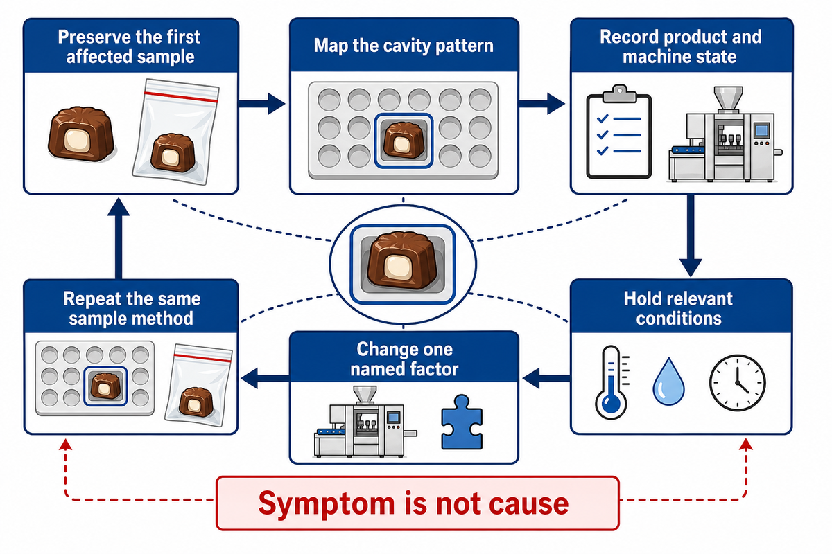
The name of a defect is the first description of a problem and isn’t an explanation of the root cause of the problem. Initially, don’t remove the affected product, and record the condition of the machine, state of the product, and the location of the defect.
| Symptom type | Preserve | Product-state check | Machine-state check | Mould/downstream check |
|---|---|---|---|---|
| Tail or string | First tail and cavity | Measured condition, hold, airflow exposure | Cut-off, pump wear, nozzle state, setting | Deposit-to-mould motion |
| Short/missing deposit | Affected row pattern | Feed continuity and bubbles | Command, motion, blockage, seal | Cavity presentation |
| Weight spread | Cavity map and weights | Hopper level and mass state | Stroke, balance, seals | Alignment and sampling point |
| Trapped air | Sectioned samples | Feed and handling history | Ingress points and feed action | Set and section method |
| Shell/core offset or leak | Cut section by cavity | Both stream conditions | Relative flow and timing | Placement, set, test condition |
| Poor release | Piece and mould location | Recipe and surface state | Dose placement | Cooling, mould, release action |
| Drip after stop | Stopped head and affected row | Mass state during hold | Close action, seals, residual pressure | Pause duration and restart result |
| Off-centre deposit | Cavity-position pattern | Flow deflection evidence | Nozzle position and index signal | Mould pitch, tracking, movement |
To investigate a defect in a production system, consider airflow, product state, wear of a pump, and the settings and actions of machine operators. Each example in the matrix should be considered alongside other examples, because no row independently proves a cause. [configuration example]
Counter-evidence rule: A before-and-after improvement is not single-cause proof when product, machine, mould, operator, batch, or ambient conditions changed together. Record simultaneous changes and test the leading explanation under controlled conditions.
Run a controlled comparison without erasing the baseline
When a defect occurs, retain and describe the affected product, record the state of the machine, and choose a working hypothesis. Describe what’s expected to change as a result of the hypothesis.
Hold
Keep recipe, batch, mould, sampling method, and relevant machine conditions fixed where practicable.
Keep recipe, batch, mould, sampling method, and relevant machine conditions fixed where practicable.
Change
Alter one named factor within the authorized operating method and record who made the change.
Alter one named factor within the authorized operating method and record who made the change.
Compare
Repeat the same cavity map, sample count, timing, and measurement method.
Repeat the same cavity map, sample count, timing, and measurement method.
Challenge
Ask which uncontrolled factor or interaction could produce the same result.
Ask which uncontrolled factor or interaction could produce the same result.
When you can’t maintain constant conditions, record the difference and lower the conclusion. The result may help to determine the next test; however, it shouldn’t be expressed as the verified root cause.
Release a Changeover with Evidence
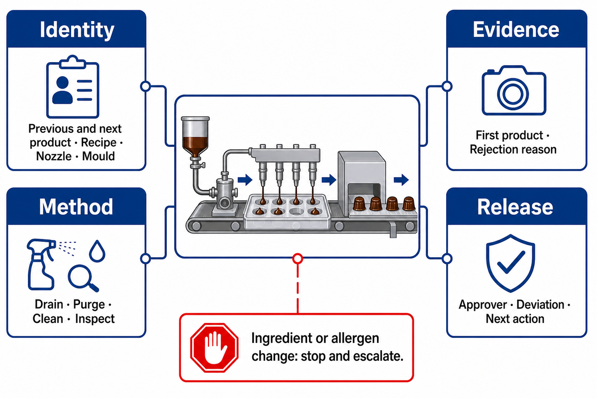
Elapsed time doesn’t allow a changeover to be released. The record must document what changed, how the product path and removable components were handled, what first product was checked, who reviewed the sample, and the rationale for accepting or rejecting the next lot. [equipment boundary]
| Identity | Previous SKU, next SKU, recipe revision, nozzle and mould identifiers |
|---|---|
| Method | Drain, purge, clean method, removable parts, inspection points |
| Evidence | Applicable residue or allergen check, first-piece sample, rejection reason |
| Release | Approver, timestamp, deviations, next action |
This format doesn’t serve as a general sanitation procedure or CIP claim. Ingredient or allergen changeovers require a stop-and-escalate decision; release authority is retained by the site’s validated food-safety program and authorized owner.
Do not invent the release rule
Residue limits, test methods, sampling locations, acceptance criteria, and authority must come from the site program. An article cannot substitute for that validation.
Cleanability and Servicing Are Review Boundaries
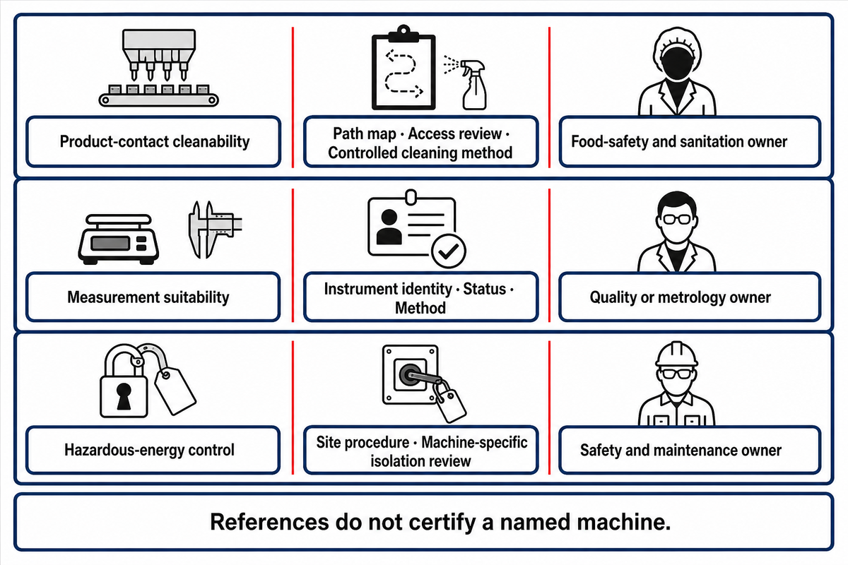
Cleanability, food-contact durability, contamination prevention, maintenance, and instrument accuracy are equipment-review inputs. 21 CFR 117.40 provides a United States regulatory boundary, while OSHA 1910.147 addresses hazardous-energy control during servicing and maintenance.
| Review input | Project evidence | Owner |
|---|---|---|
| Product-contact cleanability | Path map, access review, controlled cleaning method | Food-safety and sanitation owner |
| Measurement suitability | Instrument identity, status, range, resolution, method | Quality or metrology owner |
| Hazardous-energy control | Site procedure and machine-specific isolation review | Authorized safety and maintenance owner |
These references don’t substantiate that a particular piece of equipment is certified, compliant, guarded, validated, or released to be accepted at a customer site. The project team must consider the particular case and the situation in which the equipment will be used and deployed, as well as the pertinent local regulations.
What to Capture During Commissioning
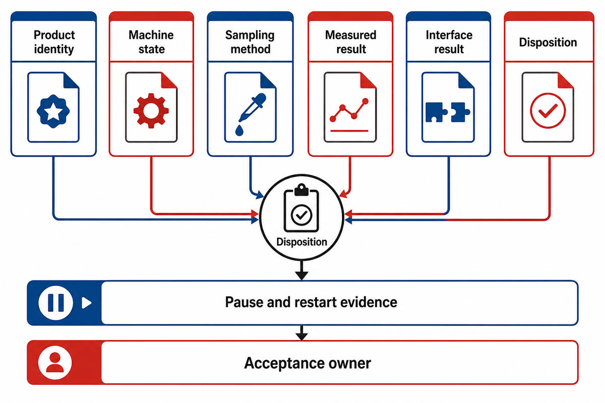
Commissioning records should connect significant process conditions and events, including unexpected interruptions and changes, to product revision, physical observations, sampling, and acceptance decisions. It should also identify instrument status, sampling location, sample count, repeat conditions, measurement resolution, and who owned the final disposition. [instrument boundary]
Product identity
SKU, recipe revision, batch, mass condition
SKU, recipe revision, batch, mass condition
Machine state
Command set, actual motion, nozzle and mould IDs
Command set, actual motion, nozzle and mould IDs
Sampling method
Cavity map, location, count, repeats, timing
Cavity map, location, count, repeats, timing
Measured result
Piece weight, visual defects, sections, resolution
Piece weight, visual defects, sections, resolution
Interface result
Cooling, release, transfer, pause/restart
Cooling, release, transfer, pause/restart
Disposition
Acceptance basis, deviation, owner, next action
Acceptance basis, deviation, owner, next action
Document instrument identity and status, the sampled process location, the sample count, repeat sampling conditions, and resolution. A logged sample alone doesn’t show whether the measurement system can distinguish the change; therefore, small samples don’t prove process capability.
Include pause and restart evidence
Record the stable run condition, stop reason, hold duration, product handling during the pause, restart sequence, first sampled cavities, and time until the agreed result returns. This separates continuous-running evidence from the operating transitions that often expose drift, air ingress, retained material, or release problems.
Record the stable run condition, stop reason, hold duration, product handling during the pause, restart sequence, first sampled cavities, and time until the agreed result returns. This separates continuous-running evidence from the operating transitions that often expose drift, air ingress, retained material, or release problems.
Company context, not product proof
SINOFUDE states that the brand was founded in 1998 and now operates three factories totaling more than 30 acres, with more than 200 employees across confectionery, baking, and chocolate divisions. Those company-level facts describe organizational context; they do not establish the performance, certification, capacity, or suitability of a named depositor.
SINOFUDE states that the brand was founded in 1998 and now operates three factories totaling more than 30 acres, with more than 200 employees across confectionery, baking, and chocolate divisions. Those company-level facts describe organizational context; they do not establish the performance, certification, capacity, or suitability of a named depositor.
The SINOFUDE technical team reviewed the documentation. The focus of the review was process terminology, distinguishing operating and business evaluations, and restricting statements concerning equipment. The final judgment concerning recipe adherence, sanitation, sample and safety procedures, and acceptance standards remains with the business process owners.
Map the depositor into your line scopeBring the recipe, product form, upstream condition, mould arrangement, cooling and release assumptions, cleaning boundary, and evidence plan.
Open the line-scope discussion
Open the line-scope discussion
Frequently Asked Questions
What is a candy depositing machine?
Short answer
A candy depositing machine meters a prepared, flowing confectionery mass and places doses into indexed mould cavities. Its working boundary may include the feed chamber, metering system, manifold, nozzles, cut-off, mould index, and controls. Cooking prepares the mass, while cooling and release determine whether the placed piece survives downstream handling; configuration depends on the product and line.
How does a candy depositing machine work?
Short answer
The machine receives conditioned mass, maintains a suitable feed state, indexes a mould, meters a dose, starts and cuts off the stream, then passes the piece to setting, cooling, and release. The sequence varies by configuration. Verify the command against observed motion, cavity placement, measured product results, and the downstream outcome instead of relying on the displayed setting alone.
Why does a candy deposit form a tail?
Short answer
A tail can be associated with product condition, local airflow, pump wear, nozzle state, cut-off behavior, operator settings, or movement between the nozzle and mould. Preserve the first affected sample and current settings, then record mass condition, command versus observed motion, cut-off, and cavity position. The symptom doesn’t establish one cause, especially when several conditions changed together.
Can one depositor make centre-filled candy?
Short answer
Only when the configuration supports the required shell and core feeds, combined head, controls, recipe conditions, section geometry, and leakage validation. Compatibility must be demonstrated for the named product and test method.
Can one temperature setting work for every hard candy recipe?
Short answer
No. A defensible setting requires the named recipe, measurement location and method, instrument status, hold history, and machine configuration.
References & Sources
- Electronic Code of Federal Regulations, 21 CFR 117.40 equipment and utensil review inputs.
- OSHA 1910.147 hazardous-energy control boundary for servicing and maintenance.
- US20050260329A1 one liquid-centre confection mechanism example.
- US20130004622A1 one timed double-deposit mechanism example.