Get in Touch with SINOFUDE Company

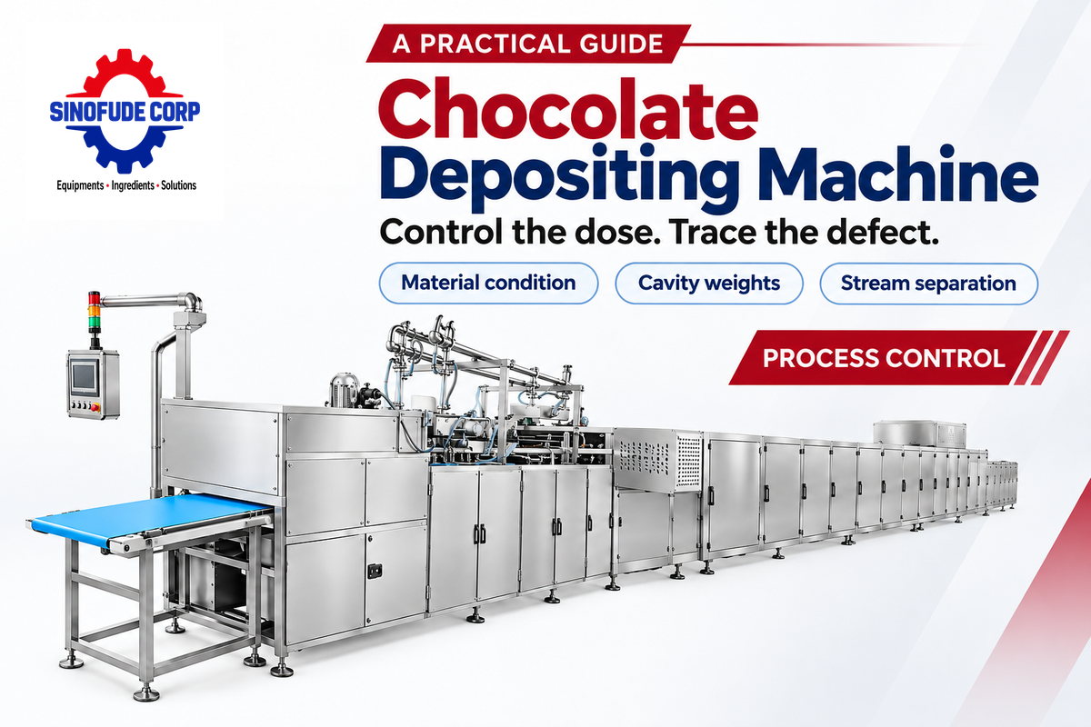
A Chocolate Depositing Machine uses fluid chocolate to meter chocolate into mould cavities or onto a receiving surface. Repeatable pieces require control of the dose, condition of the material, and path of delivery. A correct average weight can still hide a consistently light cavity, while a clean-looking deposit can develop a filling-related defect during storage.
Updated October 2026
Process at a glance
- Metering sets the delivered dose; valve closure and head motion shape the end of the stream.
- Solid chocolate uses one material stream; filled chocolate adds a separately controlled filling stream.
- Check individual cavity weights across time, then inspect shape, shell distribution and release separately.
A Chocolate Depositing Machine dispenses measured chocolate doses through a depositing head. Stable mould filling needs suitable chocolate flow, controlled metering and coordinated cut-off. Compare individual cavities over time before changing a common setting.
Key points
- Pistons and rotary valves can operate together in the same depositor.
- A heated hopper and a tempering system perform different jobs.
- One-shot depositing coordinates two streams; the filling needs its own flow baseline.
- Inspect local weight patterns, common drift and delayed defects as separate problems.
How a Chocolate Depositing Machine Works
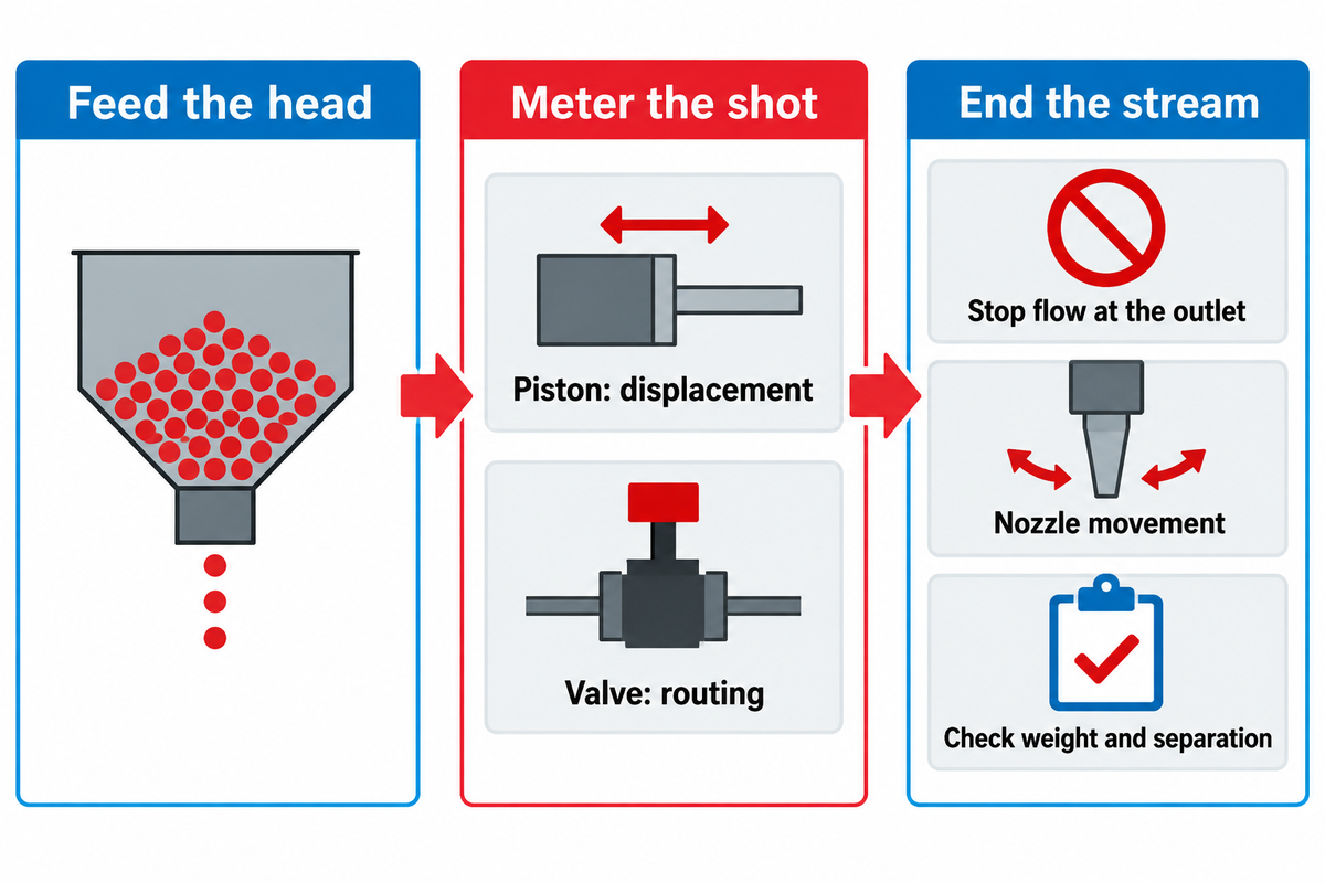
A chocolate depositor works much like a controlled syringe. It draws in a volume of chocolate and deposits that same volume through an outlet. Metering determines volume. The delivery is controlled by valves and nozzle motion. The same machine setting needs a stable recipe and condition of the feed.
A piston creates displacement inside a dosing cylinder. A valve routes chocolate into the cylinder and to the nozzle. The Aasted EP2 specifications list servo-driven pistons alongside pneumatic rotary valves. These components have different functions within a depositing system; a rotary valve can work with piston metering.
During a shot, the speed and travel of piston determine the arrival of the dose. The flow is stopped by closing the outlet. Lifting the head of the machine changes the distance between the nozzle and the deposit. Poor stream separation may leave a tail on the deposit. Increasing the dose to remove that tail changes piece weight without addressing the delivery problem.
- Feed the head. Supply chocolate in the recipe’s approved working condition.
- Meter the shot. Fill and discharge the dosing chamber through the machine’s valve sequence.
- End the stream. Coordinate outlet closure and the permitted nozzle movement before mould indexing.
For an operator, the useful distinction is visible: a low-weight piece points towards delivered quantity, while a string between successive pieces points towards stream separation. Notice both, prior to changing the control panel. Some depositing equipment offers suck-back; make use of that function only if the design of the head and the method of operation provide it.
What is the difference between a chocolate depositor and a chocolate enrober?
A chocolate depositor places a measured dose into a cavity or onto a surface; a chocolate enrober coats an existing centre as it travels through a chocolate curtain. Depositing suits mould-defined pieces and controlled fillings. Enrobing suits centres such as a wafer or formed truffle that already have their basic shape before coating.
A chocolate moulding machine can do mould handling and cooling as well as depositing. An individual confectionery machine performs a narrower task than that complete arrangement.
Control Chocolate Flow Without Losing Temper
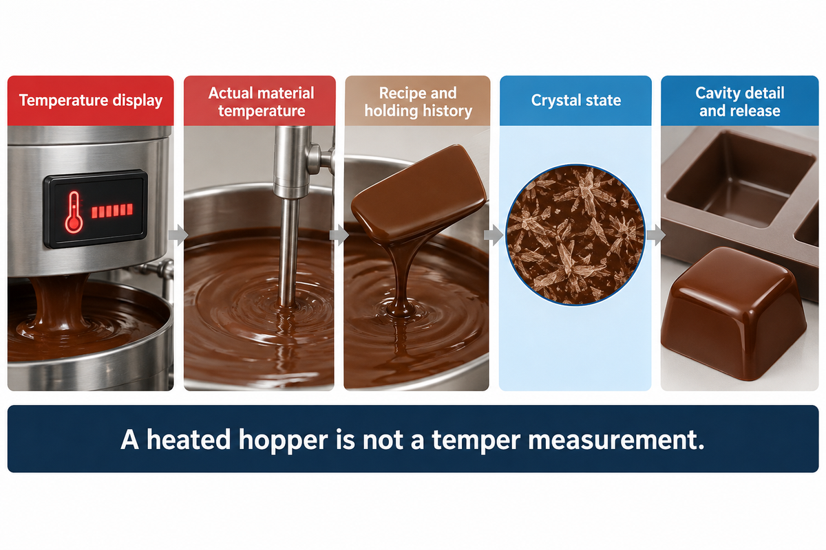
Control the fluidity of chocolate by keeping the recipe’s working condition stable via the hopper and depositing head. Fluidity affects how quickly chocolate reaches the detail of a cavity. When the depositing mass is warm and fluid, it can still have the incorrect crystal state for gloss, contraction and mould release.
Purdue Extension’s tempering guide describes controlled heating and cooling to develop suitable cocoa-butter crystals. Its moulding-temperature example applies to dark chocolate without milkfat or other fats. For milk or white chocolate production, follow the supplier’s instructions for the actual chocolate instead of Purdue’s dark chocolate example.
Callebaut’s moulded-chocolate troubleshooting guidance links holes to several conditions: inadequate fluidity, overcrystallisation, angular mould detail and trapped air. The location of the hole helps choose the next check. Missing detail at a sharp corner differs from a round air pocket inside an otherwise complete piece.
A development trial could consist of a dark couverture which fills a rounded praline cavity cleanly, and later leaves gaps after a change to a deeper, angular polycarbonate mould. The operator first assesses if all cavities are affected or if only cavities below a given nozzle are affected. Equal weights with missing corner details suggest flow is restricted and/or air is trapped, which requires attention. Lower weights at the same positions direct attention towards delivery as well. The team retains the recipe’s approved material condition and observes the vibrating table before changing a common heater setting. A larger dose would add chocolate, but could also overfill the cavities that were already complete.
Do
- Record actual chocolate temperature at the relevant process location.
- Keep recipe identity and holding history with the setting record.
- Inspect cavity detail and release after cooling.
Don’t
- Read the hopper heater display as a temper measurement.
- Change heat, dose and vibration together during diagnosis.
- Apply one chocolate supplier’s curve to every formulation.
Control Shell and Filling as Two Streams
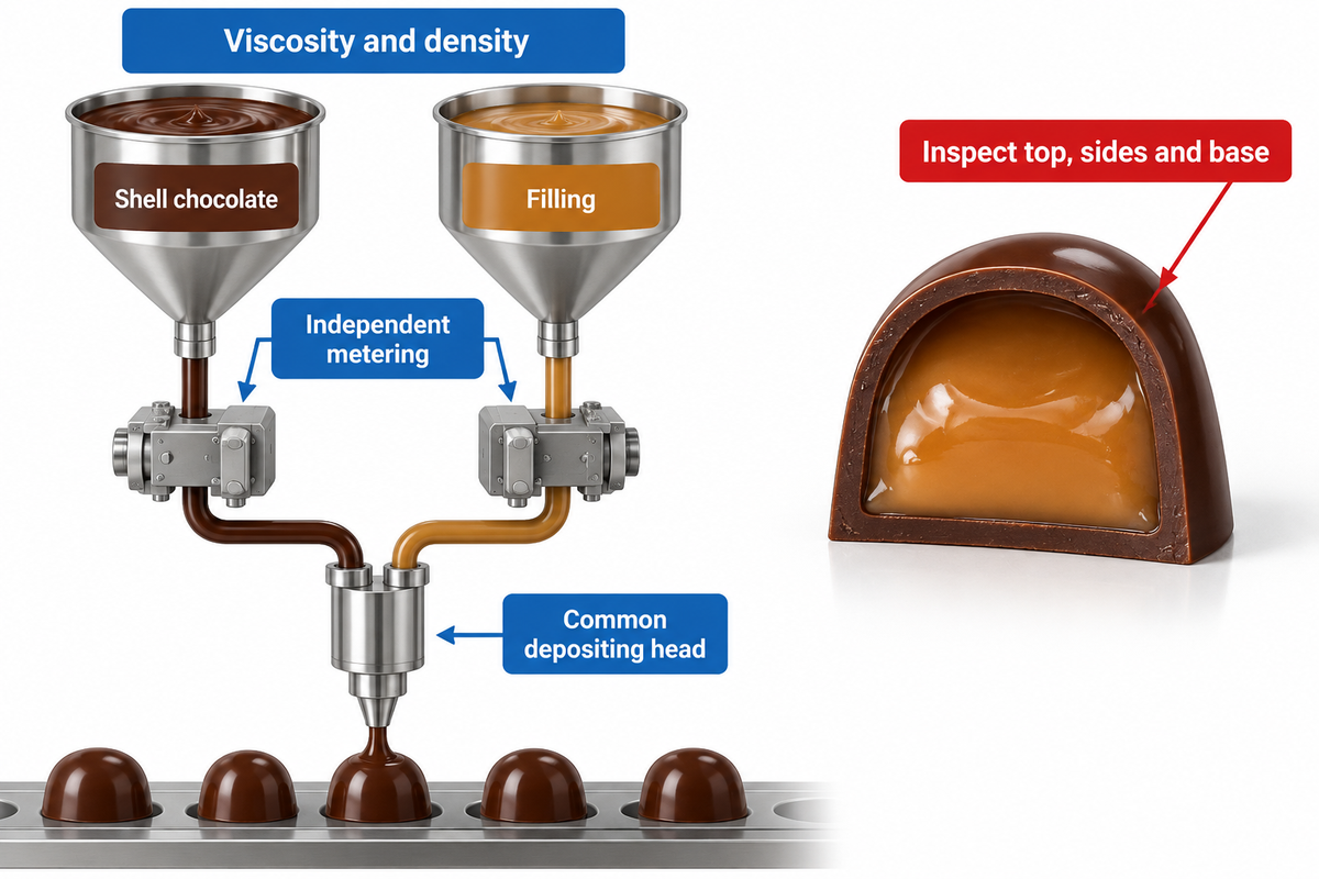
Filled chocolate requires separate control of shell chocolate and filling because the two materials flow differently and also serve different structural functions. One-shot equipment coordinates their delivery through a common head. Complete chocolate shells need sufficient material around the filling; evaluating the total piece weight does not resolve the distribution of shell material.
How does one-shot chocolate depositing work?
One-Shot chocolate depositing combines chocolate and filling in a synchronized head, usually with a central filling passage surrounded by chocolate. Amounts of each stream are controlled by independent metering. The timing and movements of the head place the filling within the chocolate deposit; start and stop sequences are determined by the particular machine design and product.
Traditional Shell moulding separates shell formation, filling, and closure into individual operations. One shot chocolate production combines material delivery in one coordinated depositing operation. Third-party published one-shot process descriptions also cover particular arrangements, including depositing on a planar surface. A sequence described for that arrangement should stay with that arrangement.
Böhme and colleagues’ 2011 study of alcoholic fillings gives formulation work on viscosity and density constraints in one-shot processing which provides an explanation for why a very fluid filling requires separate work. Ganache, nut paste and alcoholic centres cannot be treated as interchangeable fluid chocolate merely because they all pass through a hopper.
For filled bonbons, consider cooled pieces cut through the center and compare shell coverage at the top, sides and base. Keep the cavity identity. A filling that approaches one wall calls for a different investigation from a uniformly thin shell. Compare stream alignment and the filling-to-shell allocation before increasing the total dose.
For a development team moving from solid bars to filled products, the extra metering stream adds a recipe-control task. A touch screen recipe can save a sequence, but the physical filling still has to flow within that sequence. Keep separate records for each combination of shell and filling.
Match the Nozzle Path to the Mould and Recipe
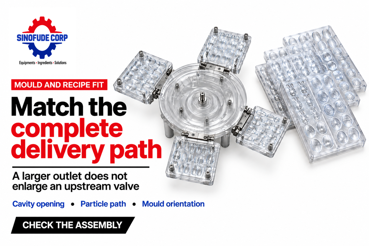
The outlet position determines the path of delivery. Match the path of delivery to the opening and depth of the cavity. Deposit chocolate within the cavity opening. Chocolate must reach the mould without striking an unintended edge or obstructing another stream. Inclusions in the head limit the path through which the recipe flows, along with the nominal size of the nozzle opening.
Aasted makes EP2 inclusion size conditional on piston diameter and deposit plate. This is a useful distinction: a large outlet doesn’t enlarge an upstream valve passage. Other factors that affect the recipe flow through depositing equipment include particle shape and loading and the carrier chocolate.
Can a chocolate depositor handle nuts, crisps, and other inclusions?
Yes, a chocolate depositor designed for inclusions can accept nuts, crisps or other particles within its specified product path. Match the largest particles and their loading to the complete dosing system. A nozzle that passes a particle once is different from a head that repeatedly feeds and meters the full inclusion recipe. Certain chocolate chips also need a suitable deposition pattern and a receiving surface rather than a praline mould.
During an R&D trial, compare the inclusion distribution of pieces from different cavities. An equal total weight can coexist with an unequal distribution of particles. Keep feed conditions the same and look at intact and sectioned samples. Increasing pressure or speed without the manufacturer’s approved procedure can turn a passage problem into damaged ingredients or equipment.
Different mold configurations change the delivery job too. A deep cavity needs a different landing path from a shallow blister. Bars, pralines and hollow chocolate use different forming arrangements, and the number of shapes of chocolates in a catalogue says little about one head’s compatibility with a specific cavity.
Make and keep a record of the nozzle plate, mould identification and orientation. Specify food-grade stainless steel for the intended food-contact application and cleaning process rather than treating the word stainless as a complete material specification. Hygienic access, seals, and spare parts need to match the intended assembly.
For an application-specific configuration, use the SINOFUDE chocolate depositing machine solution. The equipment discussion is aligned with the observations made during a recipe or process trial.
Measure Deposit Weight Across Cavities and Time
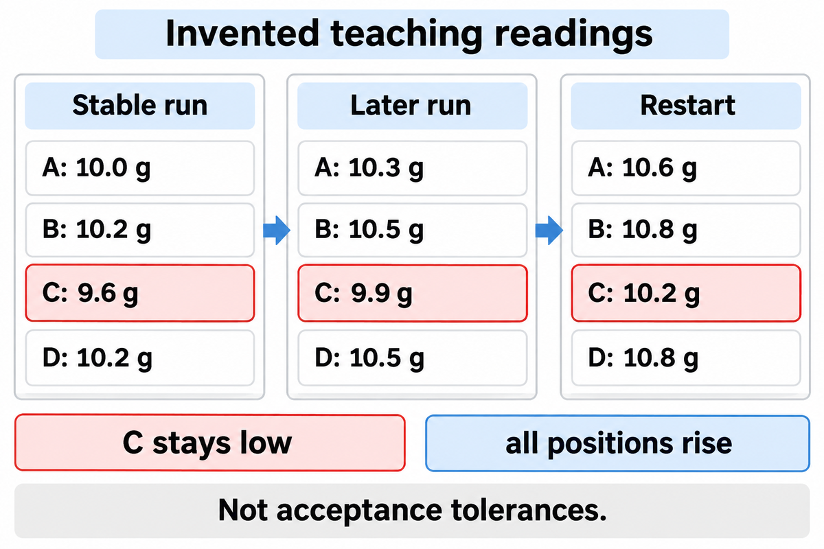
Measure individual deposit weights with cavity identity and sampling time attached. A pooled average hides discrepancies, while a single sampling moment hides variations during a run. First establish a stable weighing process: scale resolution, tare, repeatability and drift can create patterns that resemble changes in the chocolate dose.
NIST’s measurement-system guidance treats resolution, repeatability and stability as distinct issues. Reweigh an unchanged sample with the same collection methodology prior to adjusting the machine. Keep collection losses and mould tare consistent; otherwise part of the apparent deposit variation comes from measurement.
Cavity, Time Deposit Map
The Cavity-Time deposit Map compares individual shot weights by cavity and run stage and provides insight into which observation to investigate next.
They (invented readings) illustrate local and common patterns, rather than a validated sampling plan or product tolerance.
| Run stage | Cavity | Weight |
|---|---|---|
| Stable run | A | 10.0 g |
| Stable run | B | 10.2 g |
| Stable run | C | 9.6 g |
| Stable run | D | 10.2 g |
| Later run | A | 10.3 g |
| Later run | B | 10.5 g |
| Later run | C | 9.9 g |
| Later run | D | 10.5 g |
| Restart | A | 10.6 g |
| Restart | B | 10.8 g |
| Restart | C | 10.2 g |
| Restart | D | 10.8 g |
The later and restart means are 10.3 g and 10.6 g. A quality lead reviewing this example calculates the stable-run mean as (10.0 + 10.2 + 9.6 + 10.2) ÷ 4 = 10.0 g. Cavity C stays below the other positions, while every position rises together. Both these patterns are to be verified. The operator observes the C delivery path and alignment, then compares common material and feed conditions across the run stages. Adjusting a common dose to correct C would also move the other positions. The quality lead reviews the individual readings, verifies the scale is correct, and measures a further sample prior to assigning cause.
“Block what you can, randomize what you cannot.”
That experimental-design principle motivates keeping comparison conditions consistent. This observational map isn’t a randomized experiment. For product release, retain individual spread as well as the average; NIST distinguishes process control limits from product specification limits. Set acceptance against the product’s requirements and an appropriate measurement plan.
Troubleshoot Tails, Bubbles and Leaking Centres
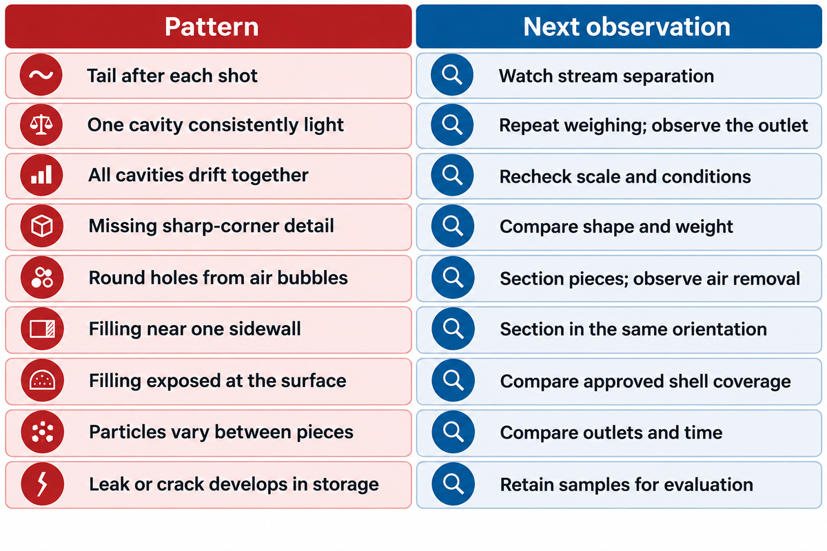
Identify at what point in a process a depositing defect appears, and choose an observation that separates competing causes. Tails concern stream separation; holes can involve flow or retained air; leaks can involve shell distribution or later material migration. A symptom should select the next check rather than dictate a single setting change.
Deposit defect-isolation matrix
Use the matrix to choose which next observation to take while holding all the other operating conditions constant.
| Defect type / pattern | Competing explanations | Next observation |
|---|---|---|
| Tail after each shot | Cut-off sequence or changed flow | Watch stream separation before comparing dose weights. |
| One cavity consistently light | Local delivery or collection error | Repeat weighing and observe the corresponding outlet. |
| All cavities drift together | Common feed, material state or scale drift | Recheck the scale and compare recorded process conditions. |
| Missing sharp-corner detail | Fluidity, crystal state or cavity geometry | Compare complete shape and weight in rounded and angular cavities. |
| Round holes from air bubbles | Entrained or retained air | Section pieces and observe the air-removal stage. |
| Filling near one sidewall | Stream alignment or shell distribution | Section identified cavities in the same orientation. |
| Filling exposed at the surface | Allocation, closure or filling behaviour | Compare shell coverage with the approved product section. |
| Particles vary between pieces | Feed distribution or restricted passage | Compare particle distribution across outlets and time. |
| Leak or crack develops in storage | Recipe migration or storage conditions | Retain dated samples for formulation and storage evaluation. |
Persistent local issues mean the equipment manufacturer’s isolation procedure needs to be performed on that path. Keep guards and interlocks in service during operating observations; isolate equipment before any access that requires it. Nozzle inspections are maintenance tasks, not reasons to reach into a running head.
Address delayed defects in other ways. Franke and colleagues’ 2022 praline-filling study reports water and ethanol migration into chocolate during storage. Keep the storage history with retained pieces. Increasing shell chocolate at the depositor is not a substitute for evaluating a filling that changes the shell over time.
Troubleshooting overfilling is addressed in the Callebaut guide as a sealing issue with staged moulded pralines. Keep that process distinction: a later closing layer belongs to shell-fill-close work, while a one-shot head controls its combined delivery. Apply the observation to the actual process instead of moving a staged praline clearance to every depositing line.
Keep Deposits Repeatable Through Stops and Changeovers
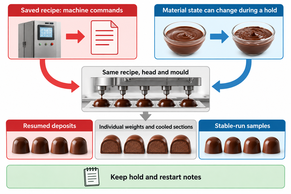
Restart with the recorded baseline for the same recipe, head and mould, then compare the first resumed deposits with stable-run samples. Chocolate can change while held at temperature because its crystal structure and flow history continue to matter. A saved recipe restores machine commands. It doesn’t restore the physical state of the material.
Hendrik and colleagues’ 2023 rheometer study distinguishes dynamic precrystallisation from subsequent static crystallisation. The apparent viscosity and yield stress of the chocolate changed during both stages. Earlier research by Hachiya, Koyano and Sato observed a period of stable viscosity of chocolate, followed by an increase in viscosity during the crystallisation.
Consider a pause in a praline recipe while the downstream conveyor is cleared. The heater display is unchanged. Upon restart, the first pieces leave tails, but cavity patterns are different from the last stable sample. The operator records the hold, checks actual material condition and observes stream separation under the approved restart procedure. The quality lead checks individual weights and cooled sections. If symptoms recover to acceptable limits over time, record the event in recipe history. The team investigates persistent symptoms and checks whether the material is in a new state. Later, a shift can tell the difference between a stable, hold-related event and a true nozzle fault.
A change from milk chocolate to dark chocolate adds a separate cleaning and allergen-control task. Process weight and appearance checks remain separate from the site’s validated cleaning and product-release procedures. Use the equipment’s approved method for sanitation. Introducing water into a chocolate circuit requires a controlled cleaning and drying procedure.
For a modular head, preserve the installed plate and seal identification with the recipe. Dozens of molds in production need traceable mould IDs, not one generic “bar” or “praline” setting. Keep the operator’s hold and restart notes with the quality record.
When a Depositor Setting Will Not Solve the Problem

Go beyond the depositor when a constraint lies in chocolate supply, cooling, transport or the product itself. A faster shot cannot feed an empty hopper, release a warm piece or stop storage migration. Diagnose the first constrained stage before buying more head speed or changing a stable depositing recipe.
Kansas State University’s food-equipment guidance explains that the slowest stage determines process capacity. In a chocolate molding line, discriminate depositing cycles from completed and accepted product. The mould feed, tempering supply, and cooling tunnel must be aligned with the same product stream.
| First constraint | What the team sees | Owner of the next check |
|---|---|---|
| Upstream supply | Hopper feed falls behind stable depositing demand | Plant manager: compare tempering and transfer supply. |
| Depositing head | Persistent local dose or cut-off pattern | Operator and maintenance: follow the identified path. |
| Cooling and release | Complete deposits but poor demoulding or downstream accumulation | Process and quality teams: inspect cooling and handling. |
| Stored product | Initially sound pieces develop cracks or leaks | Formulation and quality teams: evaluate retained samples. |
| Capital spending | More rated head capacity leaves finished output unchanged | Finance and plant manager: fund the stage limiting saleable output. |
Machine manufacturers also supply different equipment boundaries. Aasted’s EP2 is an example of a depositor; Trikno’s nozzle tempering development was detailed in a 2024 Confectionery Production interview. Compare the job each assembly performs instead of treating every chocolate making machine as an equivalent line.
A semi-automatic unit that fills one row at a time and a fully automatic chocolate moulding line require different mould handling and staffing. “universal depositor” likewise needs an application boundary: chocolate, gummies and hard candies place different material and thermal demands on chocolate machines. For chocolate products made beyond the head, the chocolate production lines guide gives the wider process route.
Frequently Asked Questions
How much does a chocolate depositor machine cost?
One PF2000 package was advertised at USD7,200 in October 2026.
TCF Sales’ PF2000 listing, checked on October 21, includes seven standard heated nozzles for row-at-a-time work. That’s a particular small-batch package. An industrial chocolate molding machine adds a different equipment scope, including mould transport and line interfaces. Use the supplied scope, tempering arrangement and cooling requirements to compare budgets; the listed package price isn’t a SINOFUDE quotation.
What production capacity can an automatic chocolate depositor reach?
The Aasted EP2 is specified at up to 20 deposits per minute, subject to product and line conditions.
Deposits per minute count machine cycles. Kilograms per hour also require the number of filled cavities, dose weight and running time. Accepted finished output further reflects rejects and downstream interruptions. Compare the same recipe and mould arrangement when assessing production capacity; a head-speed rating and a complete chocolate moulding line output describe different parts of production.
Which is better, a piston or a rotary chocolate depositor?
A piston system with a rotary valve can be the same machine; compare the metering mechanism rather than those labels.
The EP2’s documented combination shows why this isn’t a simple either/or choice. Separate the mechanism that displaces the dose from the valve that routes it. For an inclusion recipe, examine the complete particle path. For filled chocolate, examine separate stream control. Product trials should compare individual weights and sections alongside cut-off and sustained flow.
Does a heated hopper temper chocolate?
No. A heated hopper maintains temperature; tempering controls cocoa-butter crystallisation.
Some chocolate making equipment combines both functions. Identify the tempering stage and its operating method before feeding tempered chocolate to the depositing head.
Can I use the same settings for dark, milk and white chocolate?
Use a separate approved baseline for each recipe and filling combination.
Begin with the chocolate supplier’s product instructions and the depositor manufacturer’s procedure. Record actual material temperature, holding history, head sequence and mould identification. Once the process is stable, retain individual sample weights and inspect cooled pieces for cavity detail, shell coverage and release. Repeat the relevant observations after a planned hold or restart. A formulation change needs comparison with its own approved samples, even when the nominal piece weight is unchanged. Chocolatiers moving from hand-made products to automated dosing should preserve the product section and appearance they want, alongside the new machine record. Keep cleaning and allergen release separate from those process checks.
Match the equipment discussion to the product
Bring the recipe, mould format and observed production constraint to SINOFUDE’s chocolate application team. A complete cavity with a local weight problem needs a different discussion from an upstream supply shortage or a filling that changes in storage.
Technical basis: published research, material-supplier guidance and named equipment descriptions. The teaching weights and trial scenarios are editorial examples. Recipe-specific settings and release criteria belong to the approved product and equipment procedures.
References & Sources
- Purdue University Extension: Cocoa Processing, Tempering
- US20110189370A1: published one-shot process description
- Böhme et al., 2011: Tailoring alcoholic fillings for one-shot processing
- National Institute of Standards and Technology: Gauge R&R studies
- National Institute of Standards and Technology: Randomized block designs
- National Institute of Standards and Technology: Variables control charts
- Franke et al., 2022: Alcohol in praline fillings and water migration
- Hendrik et al., 2023: Chocolate tempering in a rheometer
- Hachiya, Koyano and Sato, 1988: Viscosity changes during chocolate crystallisation
- Kansas State University: Selection and Purchase of Used Food-Processing Equipment
- Confectionery Production, 2024: Trikno chocolate-tempering interview